Tonefiend Forum

Welcome Guest 

Show/Hide Header

Welcome Guest, posting in this forum requires registration.


Pages: [1] 2 3
Author Topic: Fiendmaster question
octa805

Posts: 13
Permalink
Post Fiendmaster question
on: September 11, 2012, 09:27
Quote

Hey,

neat forum! I finally got around to trying to make this sucker work and since I normally do BYOC pedals and I'm a creature of habit I used their footswitch wiring and then tried to make it fit the Fiendmaster which did not work well for me.

So I tore it apart, found your 1st project file and rewired it that way. Now I got both pots to work and it sounds pretty similar to the demo video.

I do have a few questions I'm hoping someone can help me with though

Is the gain pot just a total monster? I can't turn it past a quarter turn or else it just wants to explode my amp.

This guy is pretty hissy when on. That my poor build quality or the nature of this pedal?

I can't get the LED to work. It should be the simplest piece here but it's just befuddling me. I checked my work a few times and it looks correct and grounded on lug 5 but man, what the heck! haha. I'll try and get a pic for investigating that one.

thanks!!!!!!

joe
Administrator
Posts: 224
Permalink
Post Re: Fiendmaster question
on: September 11, 2012, 09:49
Quote

Glad you got a sound out of it! 🙂

Yes — it's frickin' loud and frickin' noisy! There will always be some residual hiss when it's on.

Send a pic of your wiring, and let's see if we can't figure out why the LED won't go.

The BYOC footswitch wiring SHOULD work great — I just prefer the way I did it because it's easier (for me at least) to visualize.

octa805

Posts: 13
Permalink
Post Re: Fiendmaster question
on: September 11, 2012, 10:16
Quote

I'm sure the BYOC wiring could work, just my brain was having trouble reconciling it for some reason.

I'll try and get to some pics later today to resolve the LED. appreciate the help.

one more thing------when I turn the tone to the bass side it seems like there is a volume jump. that sound right?

thanks again

octa805

Posts: 13
Permalink
Post Re: Fiendmaster question
on: September 11, 2012, 17:25
Quote

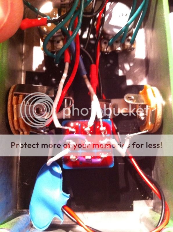
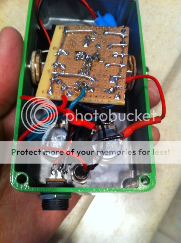
here's some quick pics I'll try and make sense of for you

I know I'm missing something easy. Thanks!

here's the footswitch. lug 5 is coming from the neg end of the lead and I believe it's being grounded on the in stereo jack on the ring?

Image

Here is the LED. As stated above, negative going to lug 5 of footswitch with the positive hitting the board at the 47k resistor.

Image

Schrodinge-
rsgoldfish

Posts: 105
Permalink
Post Re: Fiendmaster question
on: September 11, 2012, 20:36
Quote

I'm guessing you are well aware of most of the things that we'll cover here, but just to cover the basics, make sure you do all your testing with a plug in the stereo jack to complete the circuit.

If you are operating in 9-volt mode, a dying battery may power the fuzz but leave your led unlit.

Led's are polar, so if you're not certain you have the polarity right, try switching the contacts.

octa805

Posts: 13
Permalink
Post Re: Fiendmaster question
on: September 13, 2012, 07:43
Quote

Howdy! Thanks for the reply. I seriously wouldn't put any of those things past me but I think I'm clear on all of those. I just think I'm not grounding it properly somehow

octa805

Posts: 13
Permalink
Post Re: Fiendmaster question
on: September 16, 2012, 19:44
Quote

sooooooooooo, any other insights here? Maybe something from the pics? Thanks

Digital-
Larry

Posts: 192
Permalink
Post Re: Fiendmaster question
on: September 16, 2012, 21:28
Quote

Can you brute force the LED to light, like with a 9V battery and 470 ohm resistor? Maybe it accidentally took direct voltage with inadequate current limiting and "blew up"?

Also you mentioned the 47k resistor... but I just looked at the schematic - 4k7 is 4.7k, not 47k.

To deal with a pot whose useful range is small, you should attach a fixed resistor on one end (the end which is not in the useful range) and depending on the design, might need to change the pot.

E.g. you are using a 10k pot but only the first 25% is useful. Measure the resistance from the "useful" end to the wiper at this setting. That should be the value of your adjustment pot - let's say it is 2.5k. Attach a fixed resistor to make up the balance on the other end - 7.5k in this example. So now you have a 2.5k pot attached to a 7.5k fixed. The total is 10k as before and the useful range is 0 to 2.5k which is what you wanted but now spread over the full adjustment range of the pot.

It may get a bit trickier if you are using log (audio) taper pots. Specific examples always help.

octa805

Posts: 13
Permalink
Post Re: Fiendmaster question
on: September 17, 2012, 20:45
Quote

thanks for the help

the resistor is fine. I got all the parts from the mammoth kit that includes all the fiendmaster parts

I might try the pot trick later. This LED is killing me

octa805

Posts: 13
Permalink
Post Re: Fiendmaster question
on: September 18, 2012, 21:17
Quote

tonight I removed the existing LED and stuffed a new one in. Verified that I have pos & neg going to the right place. I do.

I think most likely I am just not grounding it properly. My biggest point of confusion comes from the boxing directions that are only on project #1.

Project #1 has a volume pot and is wired differently. The Fiendmaster project refers back to those boxing directions.

It's basic and should be totally easy to reconcile but I'm struggling.

So that said, let's dumb it down. What needs to get grounded on this circuit?

Lug 5 goes to ground. I have that.

The DC jack goes to ground. I have that.

what else am I missing?

Thanks!

Pages: [1] 2 3
Mingle Forum by cartpauj
Version: 1.0.34 ; Page loaded in: 0.233 seconds.

Comments are closed.